Inverting Op Amp Circuit Diagram
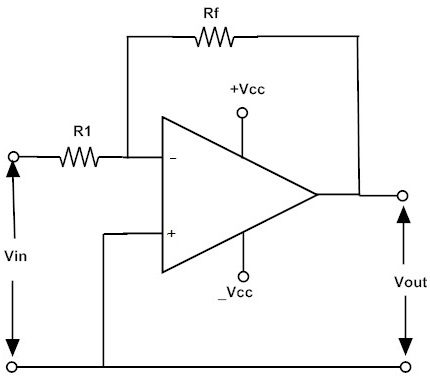
One is inverting denoted with minus sign - and other is non-inverting denoted with a positive sign. For example if Rf is 100-kilo ohm and R1 is 10-kilo ohm then the gain would be -1001010 If the ip voltage is 25v the op voltage would be 251025.
Inverting And Non Inverting Amplifier Basics Learning Corner
Op Amp Inverting Amplifier Ultimate Electronics Book
Non Inverting Opamp Electronics Lab Com
Below is the circuit diagram of a non-inverting amplifier using 741 IC and two resistors.
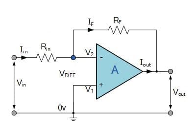
Inverting op amp circuit diagram. A typical op-amp such as shown in Figure 1 is equipped with a non-inverting input Vin an inverting input Vin and an output Vout. The circuit diagram of an inverting amplifier is shown in the following figure. The single voltage supply version of the op amp circuit for the inverting amplifier circuit uses more components when compared to the dual rail version but the design of the amplifier elements remains the same.
Schmitt Trigger Circuit Using Op-Amp. The image is divided into two gain stage. Resistors R 1 and R 2 form a voltage-divider circuit which reduces V o and connects the reduced voltage V 2 to the inverting.
LM324 is a quad op amp integrated circuit with high stability bandwidth which was designed to operate from a single power supply over a wide range of voltages. The inverting op-amp circuit diagram is shown above and the gain of the inverting op-amp circuit is generally calculated by using this formula ARfR1. Non-Inverting Amplifier Circuit Using 741 Op Amp.
The op-amp monostable multivibrator circuit is constructed around an operational amplifier configured as a closed-loop Schmitt Trigger circuit that uses positive feedback provided by resistors R1 and R2 to generate the. An inverting 741 IC op-amp comparator circuit is shown in the figure below. It is basically an inverting comparator circuit with a positive feedback.
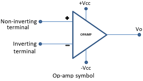
Inverting 741 IC Op-amp Comparator Circuit. An operational amplifier often op amp or opamp is a DC-coupled high-gain electronic voltage amplifier with a differential input and usually a single-ended output. It is called a inverting comparator circuit as the sinusoidal input signal Vin is applied to the inverting terminal.
Although not shown in the diagram an op-amp also has two power inputs positive and negative and may also include an offset input and other terminals. With reference to the op-amp comparator circuit above lets first assume that V IN is less than the DC voltage level at V REF V IN V REF. They have some dissimilar advantages over standard operational amplifier types in single supply applications.
In this case though the circuit. The op amp has two input terminals pins. The input voltages are applied to the inverting terminal of the op-amp.
As the non-inverting positive input of the comparator is less than the inverting negative input the output will be LOW and at the negative supply voltage -Vcc resulting in a negative saturation of the output. A non inverting operational amplifier or non inverting op amp uses op amp as main element. And another input terminal is grounded.
An inverting amplifier is a special case of the differential amplifier in which that circuits non-inverting input V 2 is grounded and inverting input V 1 is identified with V in above. That is the feedback signal is fed back to the non-inverting input and the feedback process is now positive producing a basic op-amp comparator circuit with built-in hysteresis. The fixed reference voltage Vref is give to the non-inverting terminal of the op-amp.
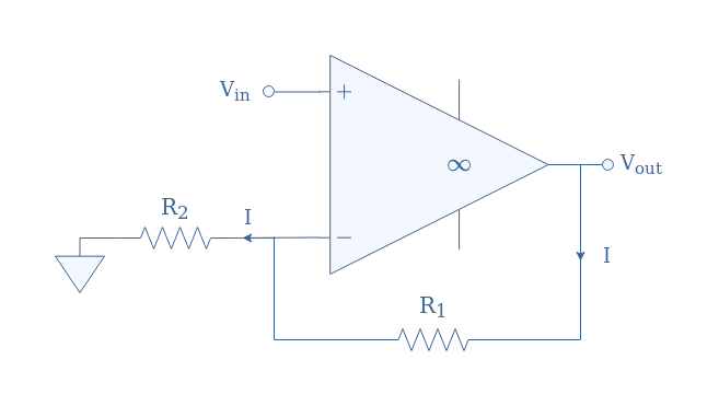
Gain A V 1 R 2 R 1. When we apply any signal to the non inverting input of it does not change its polarity when it gets amplified at the output terminal. Firstly it is showing complete closed-loop circuit as this is a closed-loop network and also the op-amps open-loop circuit because the op-amp showing A is a standalone open circuit the feedback is not directly connected.
Always used negative feedback with op-amp. Now the above-shown path with the yellow line is completed and the Op-amp is acting as an inverting amplifier if we look at point P1 the voltage is 0V as a virtual ground is formed at that point so current cannot flow through the resistor R19 and in the output point P2 the voltage is negative 07V as the op-amp is compensating for the diode drop so there is no way that current can go. Although the basic non-inverting op amp circuit requires the same number electronic components as its inverting counterpart it finds uses in applications where the high input impedance is of importance.
The purpose of the Schmitt trigger is to convert any regular or irregular shaped input waveform into a square wave output voltage or pulse. Pin Configuration of 741 Op-amp Circuit Diagram 2. Physically there is no short between those two terminals but virtually.
The simplified circuit above is like the differential amplifier in the limit of R 2 and R g very small. Effectively a half way point is created for the non-inverting input. The output is applied back to the inverting - input through the feedback circuit closed loop formed by the input resistor R 1 and the feedback resistor R 2.
Op-amp can be used to sum the input voltage of two or more sources into a single output voltage. The most widely used constant-gain amplifier circuit is the Inverting amplifier. In other words a non-inverting amplifier behaves like a voltage follower circuit.
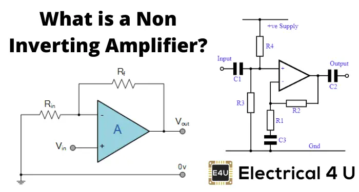
A non-inverting amplifier is an op-amp circuit configuration that produces an amplified output signal and this output signal of the non-inverting op-amp is in-phase with the applied input signal. Note that for an op-amp the voltage at the inverting input terminal is equal to the voltage at its non-inverting input terminal. In this configuration an op amp produces an output potential relative to circuit ground that is typically 100000 times larger than the potential difference between its input terminals.
The op amp non-inverting amplifier circuit provides a high input impedance along with all the advantages gained from using an operational amplifier. The closed-loop gain is R f R in hence. Below is a circuit diagram depicting the application of an op-amp as an adder or summing amplifier.
This creates ve feedback as follows. Thus it can also be called a squaring circuit. Op amp inverting amplifier using single ended supply.
The output of the summing junction is further amplified by the op-amp open-loop gain. In the inverting amplifier the input voltage is connected with the inverting- terminals of op-amp. Gain of the amplifier is given by the formula.
This arrangement is named as non-inverting because it amplifies the input signal while retaining the same polarity.
How To Build A Non Inverting Op Amp Circuit

Non Inverting Operational Amplifier Non Inverting Op Amp Electrical4u
Inverting Operational Amplifier Op Amp Circuit Design Configuration Gain Practical Examples

Example Non Inverting Op Amp Circuit Download Scientific Diagram

Op Amp Inverting Amplifier Operational Amplifier Circuit Electronics Notes
Inverting Operational Amplifiers Working And Applications

Inverting Operational Amplifier The Inverting Op Amp
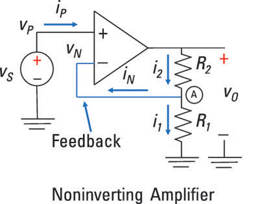
Analyze Noninverting Op Amp Circuits Dummies


